


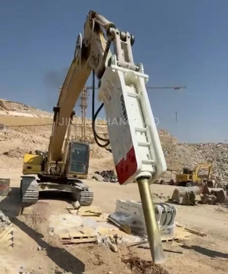
Hydraulic breaker hammer is powerful building construction equipment. As a rock stone breaking machine, the hydraulic hammer for excavator is essential construction machinery and highly efficient mining device. In engineering crushing operations such as mining, building demolition, and rock excavation, efficiency of hydraulic breaker is directly constrained by geological conditions, such as rock hardness, structural integrity, and interlayer content. The following are five core optimization techniques for different geological conditions, focusing on equipment adaptation, operating parameters, and process adjustments to achieve both improved crushing efficiency and hydraulic breaker lifespan.
Tip 1: Accurately match hydraulic breaker model and impact parameters to rock hardness.
For high-hardness geology (f > 12, such as basalt and granite):
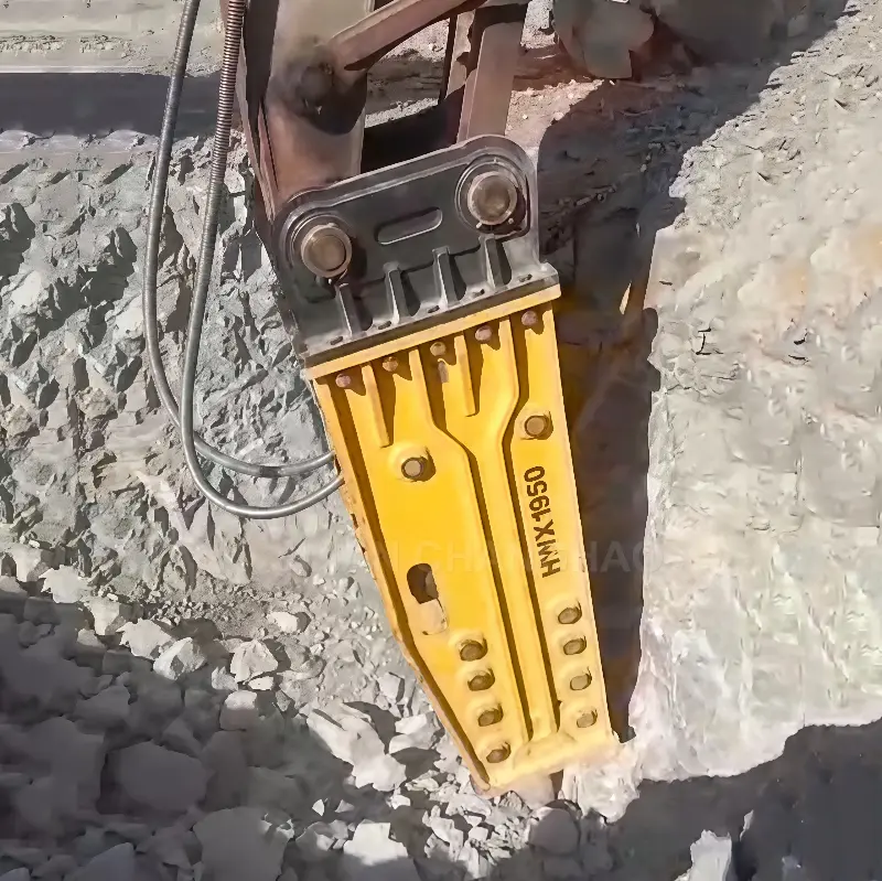
① Selection: Prioritize high-impact hydraulic breaker models (e.g., hydraulic breaker models with a chisel diameter ≥ 150mm and a strike energy ≥ 1800J). Avoid using low-impact hydraulic breaker models (e.g., chisel diameter < 100mm), as these can easily lead to chisel bending and piston wear.
② Parameter Adjustment: Adjust the hydraulic breaker’s strike frequency to a medium-to-low setting (e.g., 200-250 blows/minute) to extend the energy accumulation time of each blow. (For hard rock, use a “heavy hammer and slow strike” method to avoid energy dispersion caused by frequent, light strikes.) At the same time, adjust the hydraulic system pressure to 90%-95% of the rated pressure to avoid overpressure damage to seals.
For medium-hard geology (f=6-12, such as limestone and sandstone):
① Selection: Choose a medium-energy, high-frequency hydraulic breaker (chisel diameter 100-150mm, strike energy 1200-1800J), balancing efficiency and energy consumption. For small-scale, fine crushing operations, such as foundation pit excavation, a small hydraulic breaker (chisel diameter <100mm) can be used for increased flexibility.
② Parameter Adjustment: Adjust the strike frequency to a medium-to-high range (250-300 blows/minute) and maintain the pressure at 85%-90% of the rated pressure to achieve “medium-hardness, fast impact.”
For soft geology (f<6, such as shale, mudstone, and weathered rock):
① Selection: Avoid high-energy hydraulic breakers. Instead, prioritize small, low-energy hydraulic breakers (chisel diameter <80mm, strike energy <800J), or switch to a “hydraulic pick” (for higher efficiency in extremely soft rock).
② Parameter Adjustment: Adjust the hydraulic hammer frequency to a high setting (300-350 blows/minute) and reduce the pressure to 70%-80% of the rated pressure. At the same time, ensure the chisel penetrates shallowly into the rock (insertion depth ≤ 1/2 the chisel diameter) to prevent soft rock from adhering to the chisel and affecting subsequent hydraulic hammer strikes.
Tip 2: Optimize the hydraulic hammer strike point and operation sequence based on rock structural integrity. Rock structure (such as the degree of fracture development, the presence of joints, and the presence of interlayers) determines the “stress concentration point” during crushing. Choosing the right hydraulic hammer strike point can increase crushing efficiency by 20%-30% while reducing chisel wear.
For intact, dense rock (without cracks or joints, such as fresh granite):
① hydraulic hammer strike point selection: Prioritize hydraulic hammer strikes on rock edges or corners.
② Operation sequence: Adopt an “outside-to-inside, layered crushing” strategy—first crush the surface layer (thickness ≤ 2-3 times the hydraulic hammer chisel diameter), then work deeper layer by layer.
For rocks with developed fractures or dense joints (such as gneiss and weathered limestone):
① Impact point selection: Directly impact the “crack intersection” or “joint plane.” If the fracture is not obvious, first drill a shallow hole (50-100mm deep) in the rock surface, then strike along the hole to guide the fracture expansion.
② Operation sequence: Avoid “simultaneous crushing of large areas” and prioritize “independent small pieces of rock” (diameter less than twice the hydraulic hammer’s impact radius) before handling larger pieces. If “connected large pieces” are encountered, separate the individual pieces from the edges first, then crush them one by one (to prevent accumulation of small pieces after crushing, which could hinder subsequent operations).
For rocks with interlayers (such as sandstone with quartz interlayers and shale with argillaceous interlayers):
①Prioritize crushing “soft interlayers”: If the interlayers are argillaceous, strike the interlayer first, separating the rock into upper and lower parts along the interlayer, then crush each separately. If the interlayer is quartz, avoid it and first crush the surrounding soft rock to isolate the hard interlayer before using high-energy percussion (to avoid direct impact of the chisel against the hard interlayer, which could cause wear).
②Clean interlayer debris: During the crushing process, promptly clean fine debris (such as mud and quartz powder) generated by the interlayer to prevent it from accumulating between the chisel and the rock, resulting in “weak impact” (energy absorbed by the debris).
Tip 3: Adjust operating methods and equipment protection based on geological water content. Geological water content (such as rainy season operations, soft rock with high groundwater levels, and water-bearing karst caves) can alter rock physical properties (e.g., strong adhesion of wet soft rock and the tendency for water-bearing hard rock to splash when struck), requiring targeted adjustments to operating methods and protection.
For high-water-content geology (such as muddy areas, post-rain weathered rock, and rock containing water):
①Operational Adjustments: Avoid inserting the chisel deep into the rock (wet, soft rock tends to stick to the chisel, making extraction difficult). Instead, adopt a “shallow impact + quick pull” method (insertion depth ≤ 50mm, and immediate pull-out after impact). When encountering “water-containing hard rock,” maintain a 15°-30° angle between the chisel and the rock surface (rather than perpendicular) during impact to minimize the impact of water splashing on the operator and prevent water from entering the breaker (damaging seals).
②Equipment Protection: Install a “mud-proof sleeve” (made of rubber) at the base of the breaker’s chisel to prevent mud and water from seeping into the hydraulic joints (contaminating the hydraulic oil). After operation, promptly clean dirt from the chisel surface and lubricate the rod with lubricant to prevent rust.
For extremely high water content (such as underwater breaker operations), use a waterproof breaker (with an IP68 rating) to prevent water from entering the motor or hydraulic system. For dry and dusty geology (such as deserts and dry hard rock excavation):
① Operational Adjustment: Spray a small amount of water to reduce dust during hammering (pre-spray a layer of water on the rock surface, with a moisture content controlled at 3%-5%). Also, control the hammering frequency to avoid high-frequency hammering that causes large amounts of dust to be raised.
② Equipment Protection: Install a dust filter on the hammer’s air inlet and replace it regularly. After operation, use compressed air to clean dust from the hammer’s surface, focusing on the hydraulic interface and chisel guide sleeve.
Tip 4: Optimize Operation Techniques and Auxiliary Measures for Special Geological Conditions (Caves, Isolated Rocks, Soft Soil Foundations)
For geology with developed caves (such as limestone caves and areas surrounding underground rivers):
① Pretreatment: Before crushing, determine the location and size of the cave using geological radar or borehole detection. If the cave is below the crushing area (less than 2 meters away), backfill the cave with sand, gravel, or concrete to prevent rock from falling into the cave during crushing (causing the breaker to become suspended and the equipment to tilt). If there is water in the cave, drain the water (lower the water level to at least 1 meter below the crushing area) to prevent a sudden influx of water.
② Crushing Operation: Use low-energy, low-frequency impacts (to avoid severe impacts that could cause the cave roof to collapse). Also, assign personnel to monitor the area surrounding the crushing area (for cracks or unusual noises). Immediately shut down the machine if any abnormalities are detected.
For isolated large boulders (such as those in foundation pits or on mountain slopes):
① Fixing assistance: If the boulder is prone to rolling (such as boulders on slopes), first drill a hole in the boulder with an electric drill and insert a steel chisel and wire rope to secure it (to prevent the boulder from rolling and injuring people during crushing). If the bottom of the boulder is suspended in the air, support the bottom with wooden planks or steel sections (to prevent the boulder from tilting during impact, which would result in uneven force on the breaker).
② Crushing strategy: Start the impact from the bottom or side of the boulder (rather than the top). After the bottom is crushed, the center of gravity of the boulder moves downward, making it more stable. At the same time, the boulder is broken into smaller pieces (weighing ≤ 1/3 of the excavator’s rated load) for easier removal (reducing secondary crushing).
For hard rock under soft soil (such as swamps or hard rock beneath reclaimed land):
① Foundation reinforcement: First lay a steel plate or crushed stone cushion around the crushing area. If the soft soil depth is greater than 1m, a long auger should be used to drill holes and inject cement slurry to reinforce the soft soil (forming a hard crust to provide support for the excavator).
② Crushing Method: Use a small excavator with a short-shank hammer. Control the crushing area (single crushing area ≤ 10 m2) to avoid large-scale crushing that could destabilize the foundation.
Tip 5: Extend equipment life and ensure stable efficiency through real-time monitoring and maintenance optimization.
- Real-time Monitoring of Key Areas:
① Visual Monitoring: Every hour of operation, inspect the chisel head (for cracks, wear exceeding 10%), the guide sleeve (for blockage by dirt, increased clearance), and the hydraulic hose (for leaks, loose joints). In hard rock operations, chisel wear is 2-3 times faster than in soft rock, so inspection intervals should be shortened (e.g., every 30 minutes).
② Data Monitoring: If the breaker is equipped with an intelligent system (such as a pressure sensor or temperature sensor), real-time monitoring is available for hydraulic oil pressure (whether it exceeds the rated value), oil temperature (normal range: 30-60°C; if it exceeds 70°C, the machine must be shut down for cooling), and striking frequency (whether it is consistent with the set value; abnormalities may indicate changes in rock hardness or component seizure).
- Targeted Maintenance Optimization:
- After hard rock operations: Focus on chisel and guide sleeve maintenance. Replace chisels that are excessively worn, clean metal debris from the guide sleeve, and add high-temperature grease (hard rock operations require high oil temperatures, so a grease with a temperature resistance of 150°C or higher is recommended).
- After soft/wet rock operations: Focus on cleaning and rust prevention. Use a high-pressure water jet to flush dirt from the breaker surface, remove the guide sleeve to clean the internal debris, and apply anti-rust oil to metal parts such as the chisel and hydraulic joints (the rust rate in wet rock operations is 1.5 times that of dry rock).
- After special geological operations, such as those in caves and soft soil, the breaker’s “shock absorber” (for deformation due to impact or tilt) and “piston seal” (for wear due to dust/mud and water infiltration) should be inspected and, if necessary, replaced to prevent hydraulic oil leakage.
The above techniques can improve breaker operating efficiency by 15%-40% in diverse scenarios, including hard rock, soft rock, wet rock, and caves, while also reducing equipment failure rates (e.g., a 30% reduction in chisel breakage rates in hard rock operations and a 25% reduction in hydraulic system failure rates in wet rock operations).
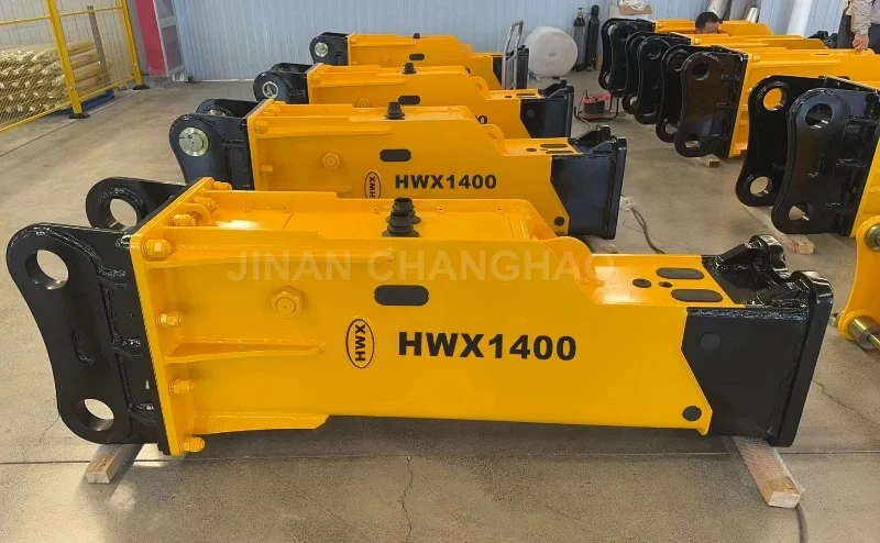
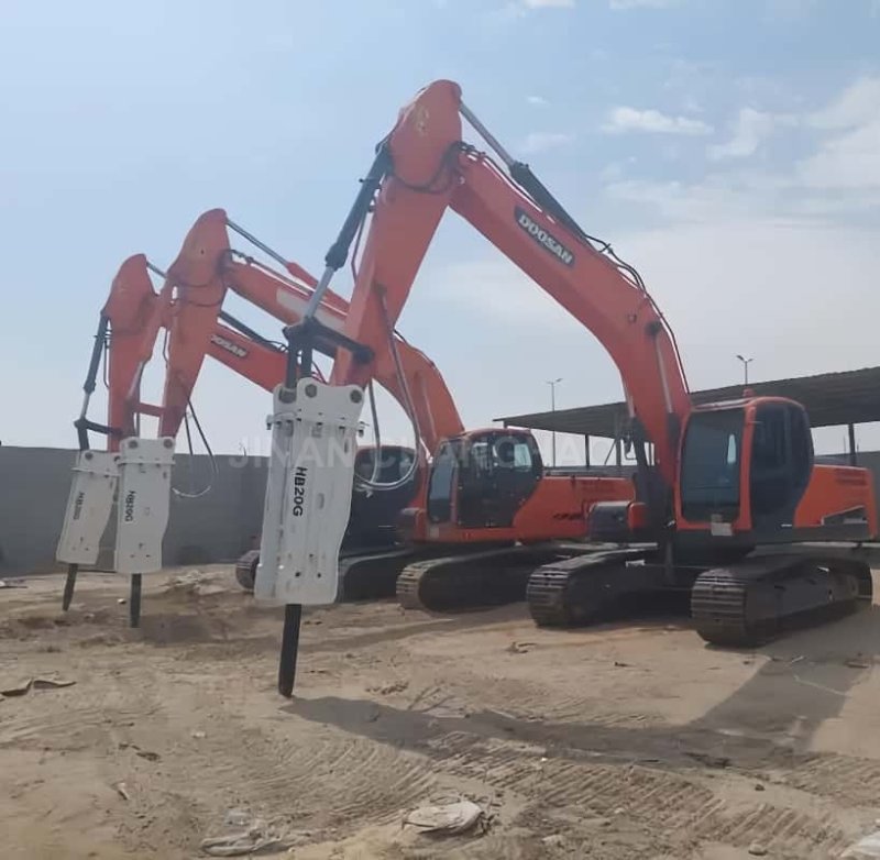
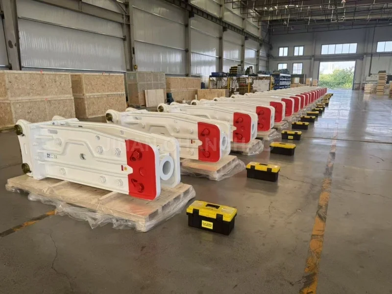
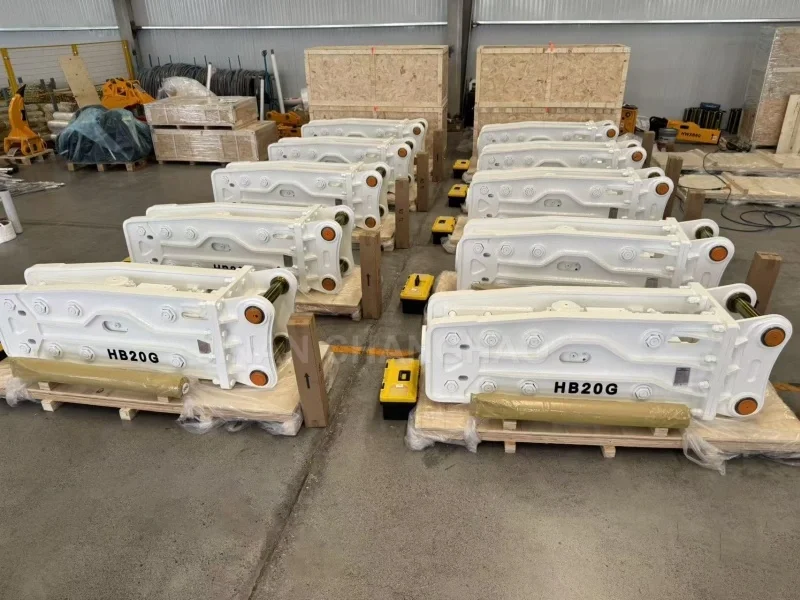
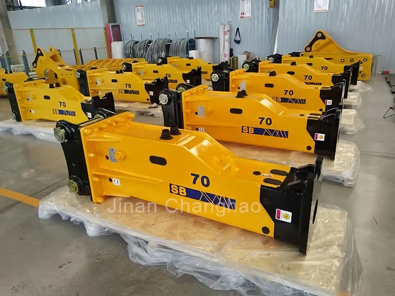
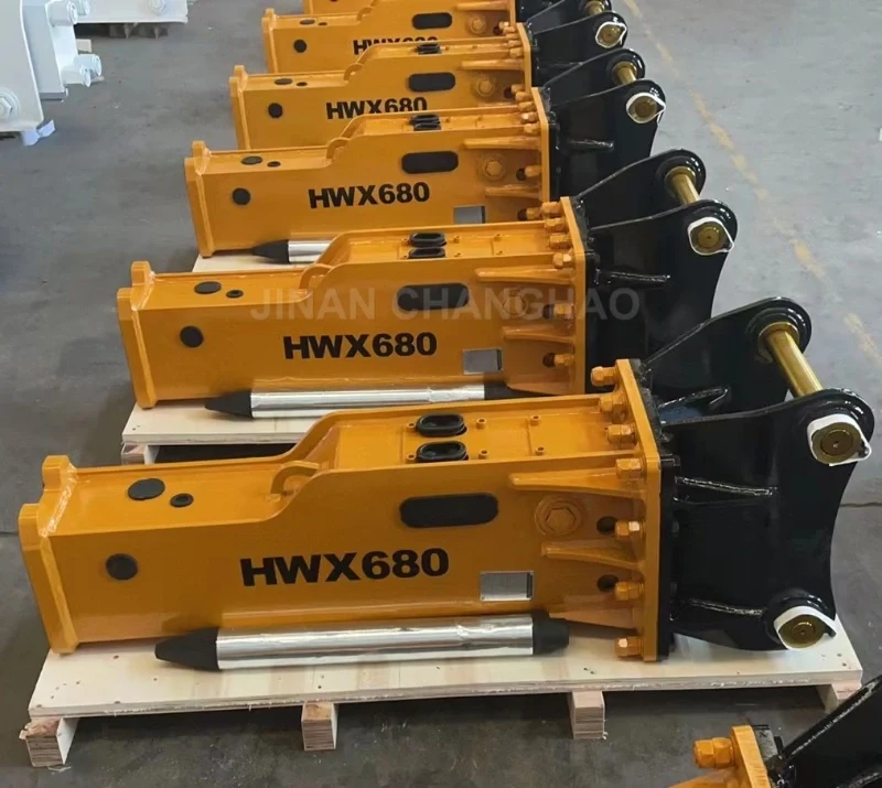
Then how to choose suitable hydraulic breaker hammers? Jinan Changhao Machinery Equipment Co., Ltd. is professional manufacturer of hydraulic breaker hammers for excavators, hydraulic breaker spare parts and other excavator attachments with over 20 years experience. We also manufacture and install hydraulic breaker piping kits with 5-year warranty for most brands excavators. Our hydraulic breaker hammers and related rock breaker pipeline kits are suitable for many brands: JCB, Volvo, John Deere, Sany, Kubota, Kobelco, Komatsu, Liugong, XCMG, Hyundai, Hitachi, CAT, Bobcat, etc. Our breaker hammer spare parts can be used as replacement for hydraulic breaker hammer of Furukawa, NPK, Atlas Copco, Rammer, Montabert, Toku, Toyo, Teledyne, MSB, Krupp, Indeco etc.
If you are interested in our hydraulic excavator breakers or Soosan/Furukawa hydraulic breaker hammer spare parts, please feel free to contact us to get best one-stop solution. Welcome to subscribe to our Youtube channel.